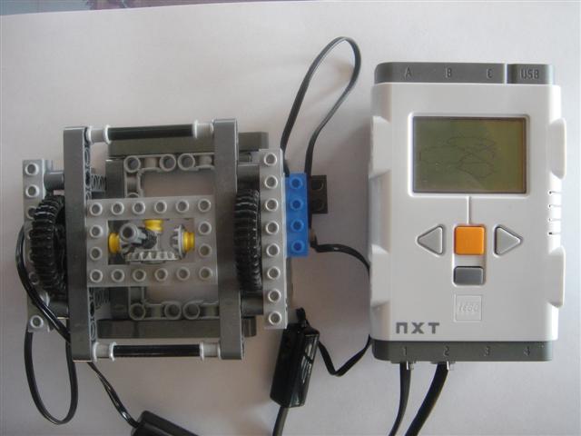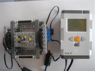
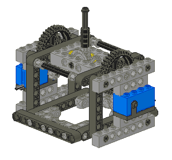
LEGO Joystick - NXT and RCX compatable
I had a few games for the NXT in mind so I decided to create a joystick for
input. I wanted something that was light weight, nimble, had a balanced center
of gravity and contained only pure (unmodified) LEGO parts. The lightweight and
nimble requirement necesitates the use of the RCX compatable rotation sensors
for the shaft encoders. The differential design keeps the center of gravity
even and prevents drag that would be caused by a moving wire if one of the
sensors was mounted in a moving position. As a consequence of using RCX
rotation sensors, this joystick is useable with the RCX.
Parts selection
I started building a joystick using only parts that came in a standard NXT set
but since the two rotation sensors are non-standard and the NXT/RCX conversion
cables are standard only in the educational version, I decided I could use other
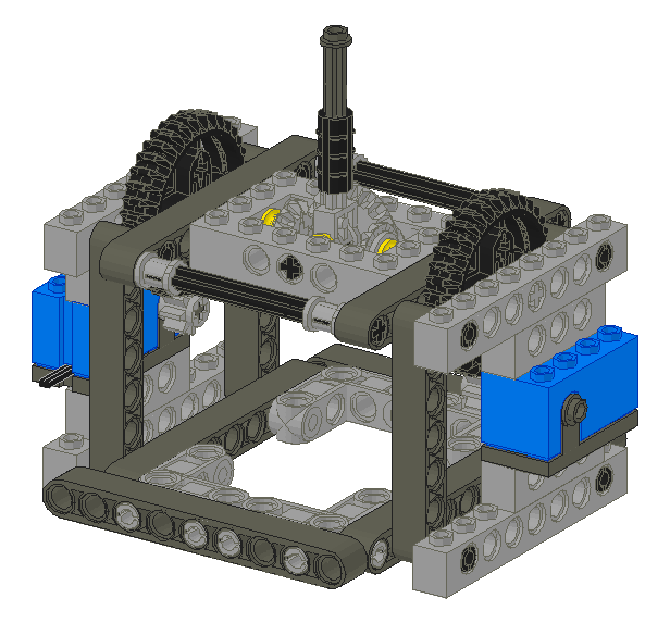
pieces as well. The most noticable non-standard piece is the 4x6 Technic Brick
that I chose as the yoke. Also, since I was using an educational set as my
base, I forgot to take into account the lack of studed beams in the retail
version. It can be assumed that anyone owning a pair of rotation sensors should
have an ample supply of studded beams lying around.
Theory of Operation
This is a differential style joystick. Moving the stick in the up-down
direction or in the left-right direction causes both shafts coming out of the
yoke to turn. Moving the stick along a diagonal keeps one shaft stationary
while the other one rotates.
People naturally expect 90°
angles to delineate up/down and left-right movement and find a mechanism with
its components oriented at a 45° angle to be counter-intuitive.
In this design, the yoke is comprised of the 4x6 brick and all pieces inside it.
Some simple calculations will
The X and Y positions are not immediatly available but may be calculated.
Notice that keeping the yoke still while moving the stick causes the stafts to
rotate at the same rate but in opposite directions. Also, keeping the stick
centered but rotating the entire yoke causes both shafts to rotate at the same
rate but this time in the same direction.
Gear selection
The major limitation of using a rotation sensor for this project is simply that
this is not an intended use for this part. The rotation sensor was designed as
a spedometer and only senses 16 steps of a 360° rotation, 22° per step.
The bad news is a joystick works best with about 90° of travel along the X
and Y axies. This design places large gears close to the stick which mesh with small gears close to
the rotation sensors to multiply subtle movements of the stick into large
movements that can be detected by the sensor. The 36 tooth gears that come with
the NXT are not intended to be meshed with 8 tooth gears but since you get a
pair of them and only one 40 tooth gear in a set, I used them. The action of
the stick would likely be smoother if 40 tooth gears were to be subsituted.
For purposes of explanation, I will refer to the X axis as moving the stick
away from one large gear towards the other and the Y axis as moving the stick
while keeping it the same distance from each of the gears.
The gear ratio of 36:8 in the X dimention causes 160° of motion on the stick
(8 rotation sensor steps) to be amplified into 720°, two complete rotations,
which is 32 steps on the rotation sensors. Note that both sensors turn the
same direction and by the same amount when this occurs.
The stick is directly attached to a 24 tooth gear which meshes with 12 tooth
gears on either side within the yoke.
Joystick Calibration
TBD
Software
Two versions of the same program are available:
Interestingly, the version made using the official LEGO NXT tools occupies 4.8MB
in the NXT memory while the NXC version only sends 3.1kB to the NXT.
Build Your Own
Follow these instructions to make your own. The
obvious prerequisite is owning a pair of rotation sensors and if this is to be
connected to a NXT, a pair of conversion cables as well.
Parts List:
| Number | Color | Part Number | Part Name |
|---|
| 2 | Light Blue | 2977C01 | Electric Rotation Sensor (Complete Assembly Shortcut) |
| 3 | Dark Gray | 6587 | Technic Axle 3 with Stud |
| 1 | Black | 3705 | Technic Axle 4 |
| 2 | Light Gray | 32073 | Technic Axle 5 |
| 2 | Black | 3707 | Technic Axle 8 |
| 1 | Black | 6538B | Technic Axle Joiner Offset |
| 4 | Light Gray | 3701 | Technic Brick 1 x 4 with Holes |
| 4 | Light Gray | 3702 | Technic Brick 1 x 8 with Holes |
| 1 | Light Gray | 40344 | Technic Brick 4 x 6 with Open Center 2 x 4 |
| 4 | Light Gray | 3713 | Technic Bush |
| 3 | Yellow | 4265C | Technic Bush 1/2 Smooth |
| 2 | Light Gray | 3647 | Technic Gear 8 Tooth |
| 2 | Light Gray | 6589 | Technic Gear 12 Tooth Bevel |
| 1 | Light Gray | 32198 | Technic Gear 20 Tooth Bevel |
| 6 | Dark Gray | 120 | Technic Liftarm 1 x 9 Straight |
| 8 | Black | 6558 | Technic Pin Long with Friction |
| 1 | Light Gray | 6553 | Technic Pole Reverser Handle |
| 2 | Black | 32498 | Technic Gear 36 Tooth Double Bevel |
| 4 | Dark Gray | 32524 | Technic Beam 7 |
| 4 | Light Gray | 55615 | Technic Beam 3 x 3 Bent with Pins |
Alternate Designs
The simplest kind of joystick from a conceptual perspective
places the two rotation sensors perpendicular to each other.
The 90° offset this gives produces X and Y readings directly.
Others have built such devices[1] but using a pure
LEGO solution requires one rotation sensor to be mounted on the yoke and this
has several consequenses. First, the electrical wire from that sensor is very
stiff and this makes the stick more difficult to position and causes an
auto-centering behavior. While the latter is a nice feature, in practice, it
forces the stick to a non-central position and the wire shifts so much that the
centering location is constantly shifting with each movement of the stick. Even
if those problems could be overcome, the center of gravity of the rotation
sensor is very difficult to position so there is another force pushing it out of
the ideal central position.
It is possible to use NXT motors as shaft encoders because of their built-in
angle sensors but a control built using these is very stiff, heavy and
susceptible to damage. As such, it is not at all suited for playing games. It
can be used in applications where the stick is expected to stay put when you
take your hand off the stick. In this mode, it is useful as a remote control
for operating another robot[2]. It is highly advised not to use the motors when
quick reflexes are required as that has a high possibility of damaging the
delicate gear train inside the motor, rendering it useless.
Other Games for the NXT
Several may be found on this german site:
http://www.nxtgames.de.vu
Footnotes
- Joysticks that output X and Y positions directly
http://tecfa.unige.ch/perso/staf/nova/blog/2006/11/21/lego-joystick/
- Joysticks that use NXT motors for shaft encoders
http://philohome.com/nxtjoystick/joystick.htm